What is Dual-Mode Bluetooth 5?

The latest release of the Bluetooth protocol, Bluetooth 5, brings greater power and control to future Bluetooth devices. So, how do you take advantage of the most advanced Bluetooth currently available and implement it into our devices today?

One of the most exciting features to be released is Dual-Mode Bluetooth. Keep reading to find out what Dual-Mode Bluetooth is, and if it is right for your design.


What is Dual-Mode Bluetooth?

Recall from a previous Symmetry blog post that Bluetooth has evolved from Bluetooth 1.0 to the current iteration of Bluetooth 5.0, and each version came with big changes in how Bluetooth devices interact with each other (read about Bluetooth 1.0 vs 2.0 vs 3.0 vs 4.0 vs 5.0 here). Between Bluetooth 3.0 and Bluetooth 4.0 came Bluetooth Low Energy, or BLE for short. BLE presented an entirely different use case, one that made Bluetooth 3.0 (also known as Bluetooth Classic) still relevant. This posed a problem for some devices that had multiple uses, like smartphones.

This is where having both Bluetooth Classic and BLE became important. We discussed this topic in another previous blog here at Symmetry (read the post here).

Dual-Mode Bluetooth 5 represents the advancement of this need. By having both Bluetooth Classic and BLE, applications can have the best of both worlds, on that incorporates powerful, long-range Bluetooth with power-saving BLE and Bluetooth MESH.


Is Dual-Mode Bluetooth Right For My Application?

The answer to whether you need Dual-Mode Bluetooth depends on how versatile you need your application to be.

Some applications are, by design, narrow in use cases. Many applications are created to do a specific job and do it well. Because many design engineers already know the specific uses of an application, these applications can be narrowed down to Bluetooth Classic or BLE.

When an application is more versatile and have the ability to scale and expand its functions over time (as is the case with many IoT devices), then having Dual-Mode Bluetooth can help future proof your device and keep it relevant in the future.

A common example of a Dual-Mode Bluetooth application is the smartphone.

If you have a modern smartphone in your pocket, it is likely equipped with both Bluetooth Classic and Bluetooth Low Energy. Because of the differences between the two, each one has its purpose.

Bluetooth Classic receives the most attention on your phone, as it allows connectivity with wireless headphones, wireless speakers, and Bluetooth enabled automobiles. When this stream is left on, you may notice the phone battery draining at a quicker rate than usual, reflecting what we know about Bluetooth Classic and its heavy energy requirements.

For less data-intensive tasks, Bluetooth Low Energy takes over, connecting the phone to devices that use smaller sensors (e.g., fitness trackers that measure your heart rate, temperature, and movement). These devices can be left on over a longer period without significantly draining your phone battery.


Okay, Dual-Mode Bluetooth Sounds Great, But Where Do I Find It?

Redpine Signals recently announced its industry-leading dual-mode Bluetooth 5 and 802.15.4 Wireless Secure MCU (WiSeMCU™) solution – RS13100 - with an integrated 180 MHz ARM® Cortex®-M4F MCU for customer applications. Redpine has been and continues to be an innovative provider of multi-protocol wireless solutions with Wi-Fi, dual-mode Bluetooth and 802.15.4, and is now leveraging its expertise and experience to launch a leading-edge dual-mode Bluetooth solution for the latest IoT audio, data and control applications.

“Dual-mode Bluetooth 5 is the technology of choice for a growing number of advanced IoT applications that require music streaming, voice recognition, and connection to smart phones and other IoT devices,” said Tim Vehling, president of Redpine Signals.“ Existing solutions in the market are either under-powered or lack support for critical Bluetooth functions, forcing designers to compromise on their designs.  The RS13100 not only features long-range dual-mode Bluetooth 5 and BLE mesh support, but also includes a high-performance processor, class-leading security, low-power operation, and advanced peripherals that meet the requirements of advanced IoT applications.”

The RS13100’s integrated ARM® Cortex®-M4F application processor is capable of running up to 180 MHz and includes a DSP co-processor ideal for accelerating compute-intensive applications such as audio and AI, providing 2-3x better performance than competitors. It has a unique combination of ultra-low power and high-performance operating modes that provide as low as 19 uA/MHz power which is the lowest in the industry. The RS13100 also supports a rich set of digital and analog peripherals including VAD (Voice Activation Detection), CAN, Ethernet, eMMC/SD Card, ADC, DAC and USB OTG.

Bluetooth Low Energy 5 and 802.15.4 integrated in the RS13100 have the capability to provide up to 20 dBm output power and -104 dBm receiver sensitivity with an internal power amplifier, making it the highest-output power solution in the industry. In addition, dual-mode Bluetooth 5 capability enables designers to provide simultaneous audio and high data throughput capabilities along with connectivity to multiple BLE and 802.15.4 devices. The integrated 802.15.4 provides ZigBee or Thread protocol support for connectivity to other home automation and sensor nodes. The RS13100 also has a unique low power operating mode for the integrated Bluetooth A2DP which provides the lowest power music streaming in the industry.

The RS13100 is based on a trusted execution environment (TEE) architecture with a separate security processor, and includes suite-B Crypto HW accelerators, secure boot, secure firmware upgrade, secure XIP and secure peripherals. Its high-security levels are ideal for applications such as mobile point-of-sale terminals, smart locks, medical devices and secure voice-based ordering. 

The RS13100 features a patent-pending ‘big-little’ architecture at every level including MCU, Bluetooth 5 as well as 802.15.4 which provides optimized transitions between high-performance and low-power operating modes. These ultra-low power capabilities enable battery-operated devices such as smart locks, fitness bands, industrial control units, sensors and location tags to have 3-4x the battery life compared with other solutions. The RS13100 also includes an "always-on" sensor-hub with hardware accelerators for voice-activity detection (VAD), sensor data collection and capacitive touch.

Redpine Signals offers the RS13100 in both package and module form-factors, including the industry’s smallest certified module with dimensions of 4.63 mm x 7.90 mm with integrated dual-mode BT 5, 802.15.4 and high-end Cortex-M4F.

Evaluation Kit for the RS13100 is available at Symmetry. Production of the RS13100 is expected to start in Q4 2018.


Features:

  • Highly integrated and secure solution with dual-mode Bluetooth 5 and 802.15.4 (capable of running ZigBee or Thread)
  • Efficient on-chip application processor based on ARM Cortex-M4F with up to 180 MHz performance, up to 4 MB dedicated flash and up to 400 kB of RAM
  • Support for BLE 5 long range (125 kbps), high data rate (2 Mbps) and advertising extensions
  • Ultra-low power consumption with multiple power modes to reduce the system energy consumption
  • Multiple levels of security including PUF (Physically Unclonable Function), Crypto HW accelerators, Secure Bootloader and Secure Zone, to create a highly secure system
  • Ultra-small size SoC (3.51 mm x 3.6 mm) and module (4.63 mm x 7.90 mm) options (additional package options are also available)
  • Integrated wireless stacks and profiles for easy evaluation and integration
  • Leading edge RF performance (up to 20 dBm output power for BLE and 802.15.4) providing long range up and higher throughputs
  • Unique peripherals like ULP sub-system, Voice Activity Detection (VAD) and up to 8 capacitive touch sensor inputs


UNDERSTANDING BLUETOOTH SECURITY

 The Bluetooth specification is huge and quite complex. As a researcher, it helps when looking at the various Internet of Things (IoT) devices to understand what a vendor of an IoT device actually implemented. This is important when one has to deal with environments where older and less secure Bluetooth implementations on older IoT devices have to interact with the new IoT devices which are capable of better security, and you have to determine what security is actually being used.

In the past, I’ve run into roadblocks while trying to figure out what was going on during various Bluetooth communications such as pairing and encryption, so I’ve put together this blog post to help explain some of the security aspects, how these aspects are typically used, and how to easily spot a few of them during a research effort.

It should be noted that this entire blog post started because I needed to explain LE Privacy in a forthcoming blog post and the “appendix” kept growing until I simply split it off into its own thing.

History

Before we explain current Bluetooth security, we should go back in time a bit. Bluetooth was invented in 1989, but really came into use during the 2000s. There is no one Bluetooth protocol; it is a collection of different protocols grouped together under a single specification. Bluetooth is managed by the Bluetooth Special Interest Group, also referred to as Bluetooth SIG.

In an effort to explain a concept like LE Privacy, we must explain a chunk of the Bluetooth history of security implementations. The “LE” in LE Privacy stands for Low Energy, but it actually has nothing to do with power consumption nor does it mean to imply there is a higher energy consumption mode involving the “Privacy” part of LE Privacy. It is actually a holdover from when there was a “larger” implementation that used more energy (Bluetooth Classic), and a “smaller” implementation when battery life was critical and energy consumption needed to be curtailed (Bluetooth Low Energy, or LE or BLE or even BTLE).

Eventually, these were combined in Bluetooth 4.0, and Bluetooth SIG chose features from both Classic and LE, based upon what was better or when one had something the other didn’t. And that is where the “LE” in “LE Privacy” came from. Remember that comment about Bluetooth being complex? Well, the naming of things like this doesn’t help.

The current standard, as of this writing, is Bluetooth 5 (there is no 5.0, it is just 5), although most devices use (and are optimized for) 4.0–4.2. As we will see later on, a lot of IoT vendors try to support legacy authentication protocols dating back as far as Bluetooth 2.0, and these can affect the quality of security.

In the OSI Model, there are seven layers—yes I can hear you groaning—but I just need to reference a few of them quickly. In the TCP/IP world, TCP is at layer 4, the transport layer. Bluetooth’s layer 4 is Logical Link Control and Adaptation Protocol, or L2CAP.

Sitting on top of L2CAP, mainly in layer 5 - the session layer - is the Security Manager, doing the whole Security Manager Protocol. It is responsible for pairing, encryption and signing. So the application sitting at layer 7 doesn’t have any information about the security stuff, it just chugs along and cares not about the lower layers’ various processes so long as it can send and receive data.

Bluetooth Smart and Bluetooth Smart Ready

As mentioned earlier, with Bluetooth 4.0 came a new security model based upon previous and new work from Bluetooth SIG. In an effort to handle requirements for devices that run off of batteries or devices that might frequently unpair and pair, the terms “Bluetooth Smart” and “Bluetooth Smart Ready” were established. These are simply groupings of characteristics, but their nature affects the security aspect of various devices, so it helps to know the background.

Bluetooth Smart is implemented on peripheral devices like headphones, speakers, fitness trackers, medical devices and so on. These devices are battery-powered and often pair to devices that they may lose contact with for extended periods of time. They may only require periodic connection to their paired host, like during data transfer. Additionally, they can maintain a pairing despite long sleep periods between wake modes—even preventing a second device from pairing.

Bluetooth Smart Ready are devices that can talk to Bluetooth Smart and use all of the capabilities. Your smartphone or your laptop are good examples of Bluetooth Smart Ready devices. If you have an old Bluetooth 2.0 or 3.0 device, Bluetooth Smart Ready can still talk to it.

While I have rarely seen the “Bluetooth Smart” or “Bluetooth Smart Ready” stickers on products (or I have ignored them), they do help illustrate the need for various security elements. For example, how does one maintain pairing in a secure fashion between a computer and a fitness tracker that will periodically upload its data? How does one secure a device or ensure the privacy of the device’s owner when the device may spend most of its time in sleep mode?

Bluetooth Security Modes

There are two security modes: LE Security Mode 1 and LE Security Mode 2. There are also four security levels appropriately numbered 1 through 4, with 4 being the most secure. Yes you can mix levels and modes. To further complicate things, there are two additional security modes named Mixed Security Mode and Secure Connection Only Mode.

We’ll start with the security levels first:

  • Security Level 1 supports communication without security at all, and applies to any Bluetooth communication, but think of it as applying to unpaired communications.
  • Security Level 2 supports AES-CMAC encryption (aka AES-128 via RFC 4493, which is FIPS-compliant) during communications when the devices are unpaired.
  • Security Level 3 supports encryption and requires pairing.
  • Security Level 4 supports all the bells and whistles, and instead of AES-CMAC for encryption, ECDHE (aka Elliptic Curve Diffie-Hellman aka P-256, which is also FIPS-compliant) is used instead.

Then the security modes:

  • Security Mode 1 is those levels without signing of data
  • Security Mode 2 is those same levels with signing of data, including both paired and unpaired communications.
  • Mixed Security Mode is when a device is required to support both Security Mode 1 and 2, i.e., it needs to support signed and unsigned data.

Secure Connection Only Mode is Secure Mode 1 with Security Level 4, meaning that all incoming and outgoing traffic in a Bluetooth device involve authenticated connections and encryption only. To complete the confusing complexity, you can run Secure Connection Only Mode with Secure Mode 2 instead of 1 to ensure all data is signed, but since the data is encrypted, and more math means more computing power, and more computing power means faster battery drain, Bluetooth SIG apparently felt encryption without signing was good enough for this particular mode.

Pairing

Now knowing what these modes and levels are, one can start to answer some of those questions about maintaining pairing despite sleep mode or enforcing privacy on a Bluetooth connection between devices that aren’t always talking to each other. But we need to discuss how they are implemented, starting with pairing.

The pairing process is pretty much where everything security-related takes place and is decided beforehand. Its purpose is to determine what the capabilities are on each end of the two devices getting ready to pair and then to get them actually talking to each other. The pairing process happens in three phases, and we will quickly outline each one.

Phase One

In phase one, the two devices let each other know what they are capable of doing. The values they are reading are Attribution Protocol (ATT) values. These live at layer 4 with L2CAP, and are typically not ever encrypted. They determine which pairing method is going to be used in phase two, and what the devices can do and what they expect. For example, ATT values will be different for a Bluetooth Smart vs a Bluetooth Smart Ready device.

Phase Two

In phase two, the purpose is to generate a Short Term Key (STK). This is done with the devices agreeing on a Temporary Key (TK) mixed with some random numbers which gives them the STK. The STK itself is never transmitted between devices. With STK, this is commonly known as LE legacy pairing. However, if the Secure Connection Only Mode is being used, a Long Term Key (LTK) is generated at this phase (instead of an STK), and this is known as LE Secure Connections.

Phase Three

In phase three, the key from phase two is used to distribute the rest of the keys needed for communications. If an LTK wasn’t generated in phase two, one is generated in phase three. Data like the Connection Signature Resolving Key (CSRK) for data signing and the Identity Resolving Key (IRK) for private MAC address generation and lookup are generated in this phase.

There are four different pairing methods:

  • Numeric Comparison. Basically, both devices display the same six digit value on their respective screens or LCD displays, and you make sure they match and hit or click the appropriate button on each device. This is not to prevent a man-inthe-middle (MITM) attack, mainly because it doesn’t, but rather to identify the devices to each other.
  • Just Works. Obviously, not all devices have a display, such as headphones or a speaker. Therefore, the Just Works method is probably the most popular one. Technically, it is the same as Numeric Comparison, but the six-digit value is set to all zeros. While Numeric Comparison requires some on-the-fly math if you are performing a MITM attack, there is no MITM protection with Just Works.
  • Passkey Entry. With Passkey Entry, a six-digit value is displayed on one device, and this is entered into the other device.
  • Out Of Band (OOB). A communication method outside of the Bluetooth communication channel is not used, but the information is still secured. The Apple Watch is a good example of this workflow. During the Apple Watch pairing method, a swirling display of dots is displayed on the watch face, and you point the pairing iPhone’s camera at the watch face while (according to Apple) bits of information are transmitted via this process. Another example is using Near Field Communication (NFC) between NFC-capable headphones and a pairing phone.

Determining Modes and Levels

As mentioned before, the Layer-7 application is not aware of the underlying Bluetooth security implementation. Therefore, reversing an app used for some Bluetooth-enabled device will not tell you the full story. Nevertheless, there are several steps you can take to determine the security modes and levels for a device.

Initiator or receiver. Determine if the device is an initiator or a receiver. In modern Bluetooth terms, it will fall into the rough categories of Bluetooth Smart or Bluetooth Smart Ready. Think of it this way: a device that initiates the Bluetooth connection during initial pairing is going to be the Bluetooth Smart Ready device. The device being paired to is going to be the Bluetooth Smart device. You will then have to prove if they are in fact Smart or Smart Ready, but knowing which is which will help determine what packets you will need to look at on a sniffer trace. Some tools will list this as Master or Slave, or some other set of terms denoting roles.

If the device you are exploring is a Bluetooth Smart receiver, you can possibly initiate the pairing from your Bluetooth Smart Ready laptop and sniff using the laptop’s Bluetooth interface as the source of your sniffing in Wireshark. See our blog post comparing hacking tools for more details.

Instructions for pairing. When you get your new Bluetooth-enabled device, it will typically include instructions for pairing. Obviously, if the devices have screens that can display a value and you can observe that Numeric Comparison or Passkey Entry is used, great. If OOB is used, even better as this is the most secure pairing method. In these cases, you know modern implementations of Bluetooth security are at least supported. If you see pairing instructions that include something like “if asked for a passcode, use xxxx” where xxxx is a four digit value, then you know Bluetooth 2.0 legacy authentication is supported, and virtually all other modern security elements are most likely not implemented.

However, most pairing involves Just Works, simply because there is no screen on many devices in the Bluetooth Smart category. If Bluetooth 2.0 legacy authentication is not supported, it does not mean additional security elements are implemented, but it helps steer further exploration.

Scanning and probing. Scanning a device with a Bluetooth scanner can help determine security levels. Any information you can get from the scans, including information on the chipset involved will help greatly. If you can determine the chipset in use, you can look up what the chipset is capable of (e.g., “it can handle up to eight connections and has AES-128 support onboard”). If the chipset “supports the latest features of Bluetooth 3.0,” then you know advanced security is not a part of the equation.

Note the MAC address. If the address is a public address and the OUI is in database with the IoT vendor’s name associated with it, they are not using LE Privacy - they are using a constant for the MAC address at all times. You can verify this over time via further scans and probes as the MAC address will remain the same.

If you can connect to the device for probing but any action seems to kick you right back out, most likely Secure Connection Only Mode is in place.

Sniffing the pairing. Detecting the implementation of security elements via a Bluetooth sniffer might seem extremely hard, but once you understand what the different security modes are and how they are used, you can easily determine what has been implemented - assuming you get a successful sniffer trace.

Ideally, you want to capture a sniffer trace of the pairing process. If you are examining the initiator or Bluetooth Smart Ready device, you want the Pairing Request packet. Conversely, if you are examining the receiver or Bluetooth Smart device, you want the Pairing Reply packet.

Bluetooth Security Manager Protocol

The opcode will be 0x01 for a Pairing Request and 0x02 for a Pairing Reply. I/O capacity will be one of the following:

  • 0x00 Display Only
  • 0x01 Display Yes/No (both a display and a way to designate yes or no)
  • 0x02 Keyboard Only
  • 0x03 No Input/No Output (e.g. headphones)
  • 0x04 Keyboard Display (both a keyboard and a display screen)
  • 0x05-0xFF Reserved

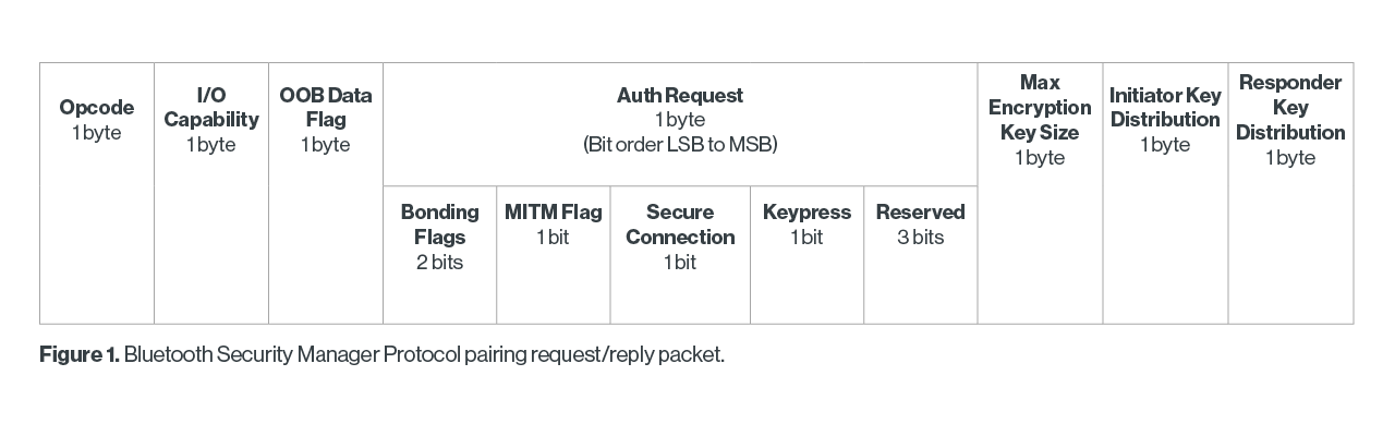
OOB Data Flag will be 0x00 for no OOB data or 0x01 for OOB data present. Max Encryption Key Size tells the size of the encryption key in octets, and both the Initiator and Responder Key Distribution bytes convey with flags what keys will be distributed.

The Auth Request byte consists of five fields, and uses the various bits as flags. From least significant bit to most significant bit, here are the fields:

  • Bonding flags, two bits, either 0 or 1 for the very least bit, the other bit is reserved. As such, 0 is for no bonding, the 1 is for bonding. If bonding is used, an LTK will be exchanged, which means two devices can be paired, and a reboot or sleep mode will not unpair the devices. If encryption is supported, this will happen separately after pairing.
  • MITM flag, one bit, 0 is that MITM protection is not requested, and 1 is that MITM protection is requested.
  • Secure connection, one bit. If this is set to 1, the device is requesting to do Secure Connection Only Mode, otherwise it is set to 0.
  • Keypress flag, one bit. If set to 1 it means Passkey Entry needs to be used, otherwise it is ignored.
  • The last three bits are reserved.

Remember though, always check your tools and do not rely on what they tell you - get multiple examples of the same process to help ensure you are sniffing the data accurately. And don’t expect every manufacturer to follow the rules as you might interpret them. Here is a Pairing Reply packet during a pairing of an Apple Watch with an iPhone using the Passkey Entry process that illustrates this perfectly:

Apple Watch Pairing Reply Packet
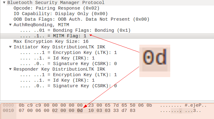
Figure 2. Wireshark interpretation of an Apple Watch pairing reply packet. Note the AuthReq section doesn’t match the raw data.

In Figure 2, the main issue is that byte 24’s (offset 0x17) value is 0x0d. Under the Wireshark interpretation, only the bits for Bonding and MITM are set, while the value of 0x0d suggests the Secure Connection bit is also set. At the time of the sniffer trace, the Passkey Entry method was chosen, but in this case, not only does the Wireshark interpretation not show it’s set, the raw data also suggests it is not set.

It should be noted that using Secure Connection Only Mode implies using either Passkey Entry or OOB as the pairing method. Since OOB is not explicitly set, the default would be Passkey Entry. This is in spite of the fact that the Keypress bit is not set.

This means either two things: 1) Since Secure Connection Only Mode was being used, Apple felt there was no reason to set the Keypress bit since it would be implied, or 2) there will be no pressing of a key on the Apple Watch side, since during Apple’s implementation of Passkey Entry no keypress is needed from the watch. My guess is the latter. During its Pairing Request packet, the iPhone did say that it can do 0x04 (Display Screen and Keyboard for input), so when you consider everything the two devices are claiming they can do in the conversation, they can handle Passkey Entry.

Overall though, during the pairing process the Apple Watch is claiming its I/O Capability is 0x00 which is Display Only, despite the fact that the Apple Watch can do a Display Screen and Keyboard input. It is specifically limiting itself during the pairing process to match what is being requested by the user, who is controlling the pairing choice. There is nothing in the specification about adjusting things to user preference or settings, although it makes sense, especially from a security perspective, to limit the amount of exposure.

This is the level of scrutiny one needs when looking at Bluetooth to either prove or disprove an action or setting. In a report or blog post on the Apple Watch, I might have simply worded this as “the Apple Watch follows the Bluetooth specification for 4.2 during the pairing process” instead of showing this level of detail. But at least you can make the statement firmly.

LE Privacy

Whenever a Bluetooth device needs to transmit, it enters an advertising mode where it announces to the world it is there. Depending upon the nature of the device, it could do this only periodically, or it could be doing this constantly. It uses a MAC address during advertising so that other devices can potentially talk back to it.

One of the issues with this scenario is that a nefarious person could track an individual’s movements by tracking where that MAC address pops up. Therefore, it makes sense that a device trying to protect its owner from tracking would periodically change its MAC address. Naturally, this creates other problems. How will the paired devices know what they are paired to if the address keeps changing? How can I limit the knowledge of my MAC address to only devices I trust, while still protecting myself from being tracked?

This is where LE Privacy comes in. This solution was introduced with the creation of Bluetooth Smart (the 4.0 standard), and it is an efficient solution for the problem. During the pairing process in phase three (as outlined above), the devices exchange a variety of keys. One of those keys is the Identity Resolution Key (IRK). This key allows for the creation and resolution of random MAC addresses to be used in advertising packets.

Basically, the real MAC address of the device isn’t really changed, just what is reported via the advertising packet is. By providing an IRK to a device’s paired partner, you are telling that partner how to “resolve” a MAC address to recognize the device later based off of its random advertising address. To help ensure the devices reconnect, the LE Privacy device will create an advertising packet with the destination MAC address of its paired partner and the random MAC address as the source - the paired partner knows to resolve the MAC address quickly to determine who it is, as it might be paired to multiple devices that use LE Privacy.

This provides a nice way for two devices to remain paired even with interruptions due to sleep mode, power cycling, or physical distance between the devices being greater than the Bluetooth range - and it still helps ensure user privacy by preventing tracking by MAC address.

LE Privacy is extremely easy to spot in a lab environment: you simply scan for MAC addresses and track them over time. By performing actions on the device with LE Privacy that will generate traffic, it will make it easier to spot. The time delay will vary and it is entirely up to the manufacturer to decide the intervals between cycles. I’ve personally seen anywhere from 15 to 30 minutes, and most devices that implement LE Privacy also use a fresh MAC address after every power cycle.

Where’s the Code?

As mentioned, this type of exploration isn’t your typical “APK decompile to get to the code that controls the Bluetooth choices” workflow, since the code for the Bluetooth stack is located in the device’s firmware or in a device driver. If it is in firmware, this can be quite complex to get to, as we’ve seen before.

Summary

Bluetooth security can be complex, but once you do a bit of sniffing and poking around in a device’s security settings (if they exist) you can learn a lot. Even by simply studying behavior, documents, and how devices interact, you can usually figure out not only what a device is capable of from a security perspective, but how much security has actually been turned on.

Secure Design for Low Energy Bluetooth (BLE) Applications

 Low Energy Bluetooth (BLE) is widely used in various smart devices and IoT scenarios as a low-power, short-range wireless communication technology. However, due to the characteristics of BLE, it is susceptible to various security threats. Therefore, when designing and developing BLE applications, it is crucial to focus on security issues and implement appropriate security measures to protect communication data and user privacy.

Firstly, Security Measures for Bluetooth Pairing

In the pairing process between BLE devices, it is essential to use FIPS-approved algorithms such as AES-CMAC and P-256 elliptic curve to ensure the security of pairing information. Pairing information should be stored in a secure storage location on the device to prevent malicious attackers from stealing it.
For authentication and encryption, FIPS-approved algorithms should also be used to ensure the confidentiality and integrity of communication data. For example, the use of AES-CCM algorithm can encrypt and protect data transmission, while also ensuring the integrity of messages. In healthcare devices, such as a health wristband communicating with a smartphone, the use of AES-CCM algorithm encrypts the user's health data to ensure its confidentiality.
To prevent passive eavesdropping and man-in-the-middle attacks, user-assisted secure simple pairing methods can be used. For instance, using the ECDHE algorithm for Simple Secure Pairing (SSP) to prevent passive eavesdropping attacks, and employing the user-assisted digital method Passkey Entry to prevent man-in-the-middle attacks.
Here is the description of the Bluetooth Simple Secure Pairing (SSP) implementation example:
Device Preparation
• Device A (Initiator): a Bluetooth device, such as a smartphone.
• Device B (Responder): a Bluetooth device, such as a Bluetooth speaker.
Pairing Steps
1. Device A and Device B both support Bluetooth 2.1 or higher and SSP.
2. Device A and Device B are both in discoverable mode, ready to pair.
3. Device A sends a pairing request to Device B, and Device B starts the pairing process upon receiving the request.
Pairing Process
1. Device B generates a random number (Nonce) and sends it to Device A.
2. Device A receives the random number and generates its own random number (Nonce), which is sent to Device B.
3. Device A and Device B both use their own random numbers and the other's random number to calculate a shared secret key (Shared Secret).
4. Device A and Device B both use the shared secret key to calculate a pairing key (Pairing Key).
5. Device A and Device B both use the pairing key to encrypt their identity information (Identity Information) and send it to each other.
6. Device A and Device B both verify each other's identity information, and if the verification is successful, the pairing is complete.
Verification Steps
1. Device A and Device B both compare the other's identity information with their own, and if they match, the verification is successful.
2. Device A and Device B both store the pairing key in their devices for future connections.

Secondly, Security Measures for Bluetooth Privacy

To protect the privacy of BLE devices, address randomization can enhance device security. By frequently changing the Bluetooth device address, it reduces the difficulty for attackers to track BLE devices over a long period. Furthermore, to reconnect known devices, the device's private address must be resolvable by other devices, which requires using the device identity resolution key exchanged during pairing to generate the private address. For example, in a retail store's iBeacon system, changing the iBeacon device's Bluetooth address frequently can prevent malicious tracking of user behavior, thus protecting user privacy.
Here is the implementation example:
Device A (BLE Device)
• Hardware: BLE microcontroller with a random number generator (RNG)
• Software: BLE stack with address randomization and pairing process implementation
Device B (Central Device)
• Hardware: BLE microcontroller with a random number generator (RNG)
• Software: BLE stack with pairing process implementation and device identity resolution key storage
Address Randomization Process
1. Device A generates a new random address (RA) using its RNG.
2. Device A sets the new RA as its Bluetooth address.
3. Device A stores the RA and a corresponding index (e.g., a counter) in its memory.
Pairing Process
1. Device A and Device B initiate a pairing process using a standard BLE pairing protocol (e.g., SMP).
2. During the pairing process, Device A and Device B exchange their respective public keys (PK_A and PK_B).
3. Device A and Device B use their public keys to generate a shared secret key (SSK) using a key agreement protocol (e.g., ECDH).
4. Device A and Device B use the SSK to generate a device identity resolution key (DIRK).
5. Device A and Device B store the DIRK in their respective memories.
Private Address Generation
1. Device A uses its RNG to generate a new private address (PA) based on the RA and the DIRK.
2. Device A sets the PA as its new Bluetooth address.
Reconnection Process
1. When Device B wants to reconnect to Device A, it uses the DIRK to generate the PA.
2. Device B sends a connection request to the PA.
3. Device A receives the connection request and verifies the PA using the DIRK.
4. If the verification is successful, Device A accepts the connection request and the two devices reconnect.
Security Benefits
• The frequent change of the Bluetooth address (RA) makes it difficult for an attacker to track the device for an extended period.
• The use of the DIRK to generate the PA ensures that only authorized devices can resolve the private address and reconnect to the device.
• The private address (PA) is not publicly visible, protecting the device's privacy.
This implementation example demonstrates how address randomization and private address generation using a device identity resolution key can enhance the security and privacy of BLE devices.

Thirdly, Security Measures for Bluetooth Denial of Service Attacks

A common form of Bluetooth denial of service attack involves attackers continuously maliciously connecting or pairing with Bluetooth devices, causing the Bluetooth channel to be occupied and therefore unusable. To prevent denial of service attacks, a Bluetooth firewall mechanism can be used. When faced with denial of service attacks, enabling a whitelist mechanism and gradually increasing the delay time for new pairing can prevent continuous brute-force attacks by malicious devices. During the delay period, only devices within the whitelist are allowed to connect, ensuring the availability of Bluetooth services. 

For example, the following is an example of the protection measures inspired by iPhone 6S unlocking attacks prevention using increasing delay times to prevent continuous brute-force attacks that render Bluetooth services unavailable. The attempt number resets after a successful connection or pairing.

ATTEMPT NUMBERNEW CONNECTION PAIRING EXECUTION DELAY
1-4None
5-91 minute
10-1410 minutes
151 hour
16-∞1 hour (max delay)

Fourthly, Security Measures for Bluetooth Relay Attacks

Relay attacks are a common Bluetooth security threat where attackers use a relay device to pass communication data between communication parties, aiming to steal sensitive information or execute malicious operations. Limiting the communication distance between BLE devices can effectively prevent relay attacks. By controlling the transmission power of BLE devices or using location technologies, the distance between communication parties can be kept within a controllable range, reducing the likelihood of relay attacks.
Implementation Example:
Device A (BLE Device)
• Hardware: BLE microcontroller with a power amplifier and a distance measurement unit (e.g., RSSI or TOF)
• Software: BLE stack with transmit power control and distance measurement implementation
Device B (BLE Device)
• Hardware: BLE microcontroller with a power amplifier and a distance measurement unit (e.g., RSSI or TOF)
• Software: BLE stack with transmit power control and distance measurement implementation
Distance-based Relay Attack Prevention
1. Device A and Device B are configured to operate at a minimum transmit power level to ensure a maximum communication distance of a given meter.
2. When Device A and Device B are paired, they exchange their respective transmit power levels and distance measurement parameters.
3. During communication, Device A and Device B continuously measure the received signal strength (RSSI) or time of flight (TOF) to estimate the distance between them.
4. If the estimated distance exceeds a predefined threshold (e.g., 2 meters), Device A and Device B will reduce their transmit power levels to minimize the communication distance.
5. If the estimated distance continues to exceed the threshold, Device A and Device B will terminate the connection to prevent a potential relay attack.

In conclusion, the application of secure design for low energy Bluetooth (BLE) needs to comprehensively consider security mechanisms such as pairing, binding, authentication, encryption, message integrity, relay protection, Bluetooth privacy, and firewall to ensure the security and reliability of BLE communication. Only by fully considering security during product design and development can potential security threats be effectively mitigated, safeguarding the security of user data and privacy.


Key2.0: Open Source Bluetooth IoT Door Lock


What is Key 2.0?

Key 2.0 (or Key20 for short) is a Bluetooth IoT Door Lock controller. It turns a conventional electric door lock into a smart door lock that can be opened using a smartphone without the need for a physical key. Thus, Key20 is the modern version of a physical key, or, as the name suggests, the key version 2.0 for the Internet of Things (IoT) era.

Key20 consists of two parts:

  1. Key20 door lock controller device, which is physically connected to the electric door lock and wirelessly via BLE to the mobile app.
  2. Key20 mobile app implementing the user interface to unlock the door and communicating with the door lock controller through BLE.
         [ Mobile Phone w/ ]
         [    Key20 App    ]
               |
               | Bluetooth Low Energy (BLE) Connection
               |
 |---[ Key20 Door Lock Controller ]---[ Electric Door Lock ]---|
 |   [           Device           ]                            |
 |                                                             |
 |                                                             |
 |                                                             |
 |----------------------(Voltage Source)-----------------------|
                        (    12 VAC    )

The following image shows the Key20 door lock controller device and the Key20 app running on a smartphone.

Key 2.0 Door Lock Controller and App

You can get a quick impression on how Key20 works watching the following video:

Key 2.0 Video

The main features of Key20 are:

  • Using state-of-the-art security mechanisms (Elliptic Curve Diffie-Hellman Key Exchange (ECDH), HMAC) to protect against attacks.
  • Open-source software and hardware, including an open implementation of the security mechanisms. No security by obscurity! Source code for the app and door lock controller as well as Eagle files (schematic and board layout) are provided.
  • Maker-friendly: using easily available cheap standard components (nRF51822 BLE chip, standard electronic parts), easy to manufacture circuit board, and open-source software and hardware design.
  • Works with BLE-enabled Android 4.3 mobile devices (and of course newer versions). Porting to other mobile operating systems like iOS should be straightforward.
  • Liberal licensing of software and hardware under the Apache License 2.0 and the CERN Open Hardware License 1.0, respectively.

Security Concepts

A door lock obviously requires security mechanisms to protect from unauthorized requests to open the door. To this end, Key20 implements the following state of the art security mechanisms.

Authorization of Door Open Requests with HMAC

All door open requests are authorized through a Keyed Hash Message Authentication Code (HMAC). A 16 byte nonce (big random number) is generated by the door lock controller for each door open request as soon as a BLE connection is made to the door lock controller. The nonce is sent to the mobile app. Both, the nonce and the shared secret, are used by the mobile app to calculate a 512 bit HMAC using the SHA-2 hashing algorithm, which is then truncated to 256 bits (HMAC512-256), and sent to the door lock controller. The door lock controller also calculates an HMAC based on the nonce and the shared secret, and only if both HMACs match, the door will be opened.

The nonce is only valid for one door open request and effectively prevents replay attacks, i.e., an attacker sniffing on the radio channel and replaying the sniffed HMAC later. Note that the BLE radio communication is not encrypted, and it actually does not need to be encrypted since a captured HMAC is useless when re-played.

Moreover, each nonce is only valid for 15 s to prevent man-in-the-middle attacks where an attacker intercepts the HMAC and does not forward it immediatelly but waits until the (authorized) user walks away after he is not able to open the door. Later the attacker would then send the HMAC to the door lock controller to open the door. With a time window of only 15 s (which could be reduced further), such attacks are futile since the authorized user will still be at the door.

Note that the whole authentication procedure does not include heavy-weight asymmetric crypto functions, but only light-weight hashing algorithms, which can be performed on the door lock device featuring an nRF51822 micro-controller (ARM Cortex M0) very fast in order not to delay door unlocking.

With respect to the random nonce we would like to note the following. First, the nRF51822 chip includes a random number generator for generating random numbers from thermal noise, so nonces should be of high quality, i.e., truly random. An attack by cooling down the Bluetooth chip to reduce randomness due to thermal noise is not relevant here since this requires physical access to the lock controller installed within the building, i.e., the attacker is then already in your house.

Secondly, 128 bit nonces provide reasonable security for our purpose. Assume one door open request per millisecond (very pessimistic assumption!) and 100 years of operation, i.e., less than n = 2^42 requests to be protected. With 128 bit nonces, we have m = 2^128 possible nonce values. Then the birthday paradox can be used to calculate the probability p of at least one pair of requests sharing the same nonce, or, inversely, no nonces shared by any pair of requests. An approximation of p for n << m is p(n,m) = 1 - e((-n2)/(2*m)), which practically evaluates to 0 for n = 2^42 and m = 2^128. Even for n = 2^52 (one request per us; actually not possible with BLE), p(252,2128) < 3e-8, which is about the probability to be hit by lightning, which is about 5.5e-8.

Exchanging Keys with Elliptic Curve Diffie Hellman Key Exchange (ECDH)

Obviously, the critical part is the establishment of a shared secret between the door lock controller and the mobile app. Anybody in possession of the shared secret can enter the building, thus, we must ensure that only the lock controller and the Key20 app know the secret. To this end, we use Elliptic Curve Diffie-Hellman (ECDH) key exchange based on Curve 25519. We assume that the door lock controller is installed inside the building that is secured by the lock---if the attacker is already in your home, the door lock is futile anyway. Thus, only the authorized user (owner of the building) has physical access to the door lock controller.

First, the user needs to press a button on the door lock controller device to enter key exchange mode (the red button in the pictures). Then both, the mobile app and the door lock controller calculate different key pairs based on the Elliptic Curve 25519 and exchange their public keys, which anyone can know. Using the public key of the other party and their own private keys, the lock controller and the app can calculate the same shared secret.

Using Curve 25519 and the Curve 25519 assembler implementation optimized for ARM Cortex-M0 from the Micro NaCl project, key pairs and shared secrets can be calculated in sub-seconds on the nRF51822 BLE chip (ARM Cortex M0).

Without further measures, DH is susceptible to man-in-the-middle attacks where an attacker actively manipulates the communication between mobile app and door lock controller. With such attacks, the attacker could exchange his own public key with both, the lock controller and the app to establish two shared secrets between him and the door lock controller, and between him and the mobile app. We prevent such attacks with the following mechanism. After key exchange, the mobile app and the door lock device both display a checksum (hash) of their version of the exchanged shared secret. The user will visually check these checksums to verify that they are the same. If they are the same, no man-in-the-middle attack has happened since the man in the middle cannot calculate the same shared secret as the door lock controller and the mobile app (after all, the private keys of door lock controller and mobile app remain private). Only then the user will confirm the key by pressing buttons on the door lock controller and the mobile app. Remember that only the authorized user has physical access to the door lock controller since it is installed within the building to be secured by the lock.

The following image shows the mobile app and the door lock controller displaying a shared secret checksum after key exchange. The user can confirm this secret by pushing the green button the the lock controller device and the Confirm Key button of the app.

Key Exchange with Checksum

Why not Standard Bluetooth Security?

Actually, Bluetooth 4.2 implements security concepts similar to the mechanisms described above. So it is a valid question why don't we just rely on the security concepts implemented by Bluetooth?

A good overview why Bluetooth might not be as secure as we would like it to be is provided by Francisco Corella. So we refer the interested reader to his page for the technical details and a discussion of Bluetooth security. We also would like to add that many mobile devices still do not implement Bluetooth 4.2 but only Bluetooth 4.0, which is even less secure than Bluetooth 4.2.

So we decided not to rely on Bluetooth security mechanisms, but rather implement all security protocols on the application layer using state of the art security mechanisms as described above.

Bluetooth Door Lock Controller Device

The Door Lock Controller Device needs to be connected to the electric door lock (2 cables). You can simply replace a manual switch by the door lock controller device.

The door lock controller needs to be placed in Bluetooth radio range to the door and inside the building. Typical radio ranges are about 10 m. Depending on the walls, the distance might be shorter or longer. In our experience, one concrete wall is no problem, but two might block the radio signal.

Door Lock Controller Hardware

The door lock controller hardware is designed for operating AC (alternating current) electric door locks, which typically run from 6-12 VAC.

The hardware design (schematics and board layout for Eagle) for the door lock controller device can be found in folder pcb/key20-ble.

The following images show the hardware and schematic. The hardware basically concists of one circuit board (PCB). We deliberately used a simple single-sided through-hole design to help makers producing their own boards. An LCD, a power switch, and two push buttons for user interaction are connected to the main PCB. An ob-board voltage regulator provides 3.3 V fed by an external DC power supply (anything between 4 V and 30 V will work). The circuit draws less than 50 mA when the lock is operated, thus, you can use a cheap 5.0 V USB power supply. With a little modification, we could also switch off the LCD when not needed, and the device could run from 4 AA-size batteries most probably for years.

Key 2.0 PCB and LCD

Key 2.0 Schematic

The main part of the hardware is an nRF51822 BLE chip from Nordic Semiconductors. You can buy so-called "Bluetooth 4.0" breakout boards with an nRF51822 (version 3, variant AA w/ 16 kB of RAM and 256 kB flash memory) and two 2x9 connectors (2 mm pitch) for about 6 US$ including shipping. To connect the Bluetooth 4.0 board hosting the nRF51822, the PCB has two 2x9 pin connectors (no SMD soldering required). The nRF51822 features an ARM Cortex M0 micro-controller and a so-called softdevice implementing the Bluetooth stack, which runs together with the application logic on the ARM Cortex M0 processor. Key20 uses the S110 softdevice version 8.0 (see next sub-section on how to flash the softdevice and the Key20 application code).

The nRF51822 operates the electric door lock through a TRIAC. Note that most electric door locks use alternating current (AC), so a transistor will not work. We have added a snubber circuit (capacitor and resistor) to drive the inductive load (electric door lock) since TRIACs are sensitive to sudden voltage jumps possibly leading to unwanted turn-on, i.e., door unlocking. The TRIAC is operated in quadrant 2 and 3 (current flowing out of the gate) to avoid the less sensitive quadrant 4. Since the TRIAC needs about 30 mA to trigger reliably, a transistor is used to drive the TRIAC by the nRF51822, reducing the current on the micro-controller's GPIO to less than 1 mA.

Note that our design is targeting electric door locks using small AC voltages (typically 6-12 V AC). Theoretically, the TRIAC can drive 230 V loads up to 16 A. However, for safe 230 V and higer current operation the design has to be adapted, e.g., X2 snubber capacitor, isolation of the low-voltage part (3.3 V microcontroller) from the 230 V part through an opto-TRIAC, larger trace width and distances, etc.

An LCD is used to implement the secure key exchange procedure described above (visual key verification to avoid man-in-the-middle attacks). We used a common HD44780-compatible LCD display with 2x16 characters (1602A, 2-3 US$ including shipping). The LCD is connected to the main PCB through a ribbon cable. We designed a custom adapter board for connecting and mounting the 1602A LCD (see folder pcb/lcd1602a-connector).

Lock Controller Software

Overview

The software for the door lock controller can be found in folder nrf51.

Keys (shared secrets) are persistently stored in flash. Currently, we store 4 keys, but you can easily increase this number up to the limit of the flash size (nRF51822 version 3, variant AA comes with 256 kB flash, and each key consumes only 32 bytes).

Application events and a state machine approach are used to implement the application logic. Events are handled outside the interrupt context to avoid blocking the softdevice. In particular, actions like calculating keys or hashes can take significant time, although the crypto implementations used by Key20 can also process such compute-heavy tasks in just hundreds of milliseconds.

A lean-and-mean library was implemented for the nRF51822 chip to drive the LCD.

For more details, please have a look at the source code.

Prerequisites for Building the Software

No heavy-weight IDE is required to build the code. However, still a few tools are required to build and flash the code (tested with the given version numbers):

Building and Flashing the Software

First, adapt the Makefile by defining the following variables:

  • NRF51_SDK: path to the nRF51 SDK directory
  • CROSS: path to the compiler tools
  • CFLAGS: add -DTARGET_BOARD_NRF51DK if you compile for the nRF51 Development Kit (DK); if this definition is not set, you compile for the Key20 board.
  • LINKER_SCRIPT: set to nrf51422_ac_s110.ld for the nRF51 DK (nRF51422, variant AC) or to nrf51822_aa_s110.ld for the Key20 board (nRF51822, variant AA).

Compiling the code:

$ cd nrf51
$ make

Flashing the softdevice:

$ nrfjprog --family NRF51 --program s110_nrf51_8.0.0_softdevice.hex --chiperase --verify

Flashing the application:

nrfjprog --family NRF51 --program key20.hex --verify --sectorerase

Rebooting after flashing:

nrfjprog -r

Android App

The source code of the Key20 app for Android can be found in folder android/Key20. The code was developed with Android Studio 2.1.

The app requires a BLE-enabled mobile device running Android version 4.3 "Jelly Bean" (API level 18) or higher.

The following images show the two major tabs of the app: one for opening the door, and the second for exchanging keys between the app and the door lock controller.

Key 2.0 App: Unlock Tab
Key 2.0 App: Key Exchange Tab


Building a Bluetooth Low Energy Powered Expo App Guide

In this easy-to-follow tutorial, we'll take you by the hand and show you how to seamlessly integrate Bluetooth Low Energy (BLE) into you...